
Product images are illustrative; actual items may vary. Core functionality remains unaffected.
Honyee Stepper Drive and Motor Solutions
Reliable and cost-effective motion control for a wide range of applications.
* All prices are net prices (without VAT) and do not include transport costs, which will be added in the order.
Honyee Stepper Drive and Motor Solutions
$100.00
- 24/7 Online Support
- 12 Months Warranty for New Products
Honyee Stepper Drive and Motor Solutions
$100.00
- 24/7 Online Support
- 12 Months Warranty for New Products
Honyee Stepper Drive and Motor Solutions
Digital Two-Phase Open-Loop Driver
| Model | HK430 | HK542 | HK556 | HK556S | HK872 | HK860 |
|---|---|---|---|---|---|---|
| Phase | 2 phase | |||||
| Dial switch |
|
|
||||
| Current | 0.10-2.20A | 0.71-3.00A | 1.00-4.00A | 2.00-6.00A | ||
| Peak current | 0.14-3.00A | 1.00-4.20A | 1.40-5.60A | 2.40-7.20A | ||
| Supply voltage | DC12-40V | DC12-75V | DC24-90V AC18-60V |
DC24-110V AC18-80V |
||
| Subdivision parameter | 200-20000 P/R | 200-25600 P/R | 400-51200 P/R | |||
| Electric frequency signal | 5-24V compatible No series resistor required |
|||||
| Control method | Pulse+direction/double pulse | Pulse+direction | Pulse+direction/double pulse | |||
| Maximum pulse frequency | 500KHZ Factory default 200KHZ |
|||||
| Signal interface |
|
|||||
| Motor wiring | A+(Black) A-(Green) B+(Red) B-(Blue) | |||||
| Debug port | type-c | RJ11 | ||||
| Protection | Overvoltage/undervoltage/overcurrent | |||||
| Color | Black | |||||
| Dimensions | 93 * 56 * 21 | 118 * 76 * 33 | 151 * 98 * 47 | |||
| Adaptive motor | 28/35/42 base open loop motor | |||||
| Certificate | CE/FCC | |||||
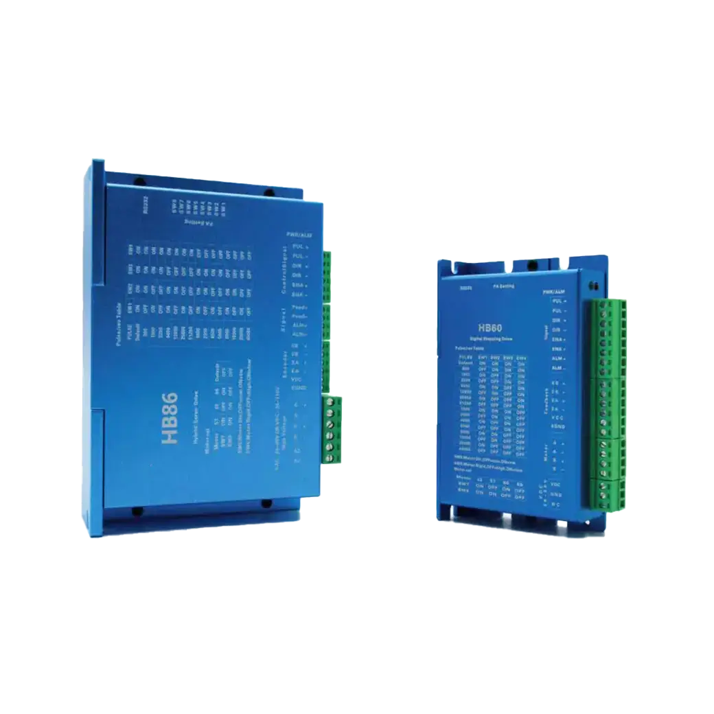
Digital Two-Phase Closed-Loop Driver
| Model | HB60 | HB86 |
|---|---|---|
| Phase | 2 phase | |
| Dial switch |
|
|
| Current | 8A | |
| Peak current | 13A | |
| Supply voltage | DC20-80V | DC24-110V / AC20-80V |
| Subdivision parameter | 400-51200 P/R | |
| Electric frequency signal | 5-24V compatible No series resistor required |
|
| Control method | Pulse + direction / double pulse | |
| Maximum pulse frequency | 500KHz Factory default 300KHz |
|
| Signal interface |
|
|
| Motor wiring | A+ (Black) A- (Green) B+ (Red) B- (Blue) | |
| Encoder wiring | EGND (Black) VCC (Red) EA+ (Blue) EA- (Blue-Black) EB+ (Green) EB- (Green-Black) | |
| Debug port | RJ11 | |
| Protection | Overvoltage / undervoltage / overcurrent / overproof | |
| Color | Sand black / Sand blue | Sand blue |
| Dimensions | 116 x 70 x 27 | 151 x 97 x 52 |
| Installation size | 108 | 139 |
| Adaptive motor | 42/57/60 base closed loop motor | 86 base closed loop motor |
| Certificate | CE / FCC | |
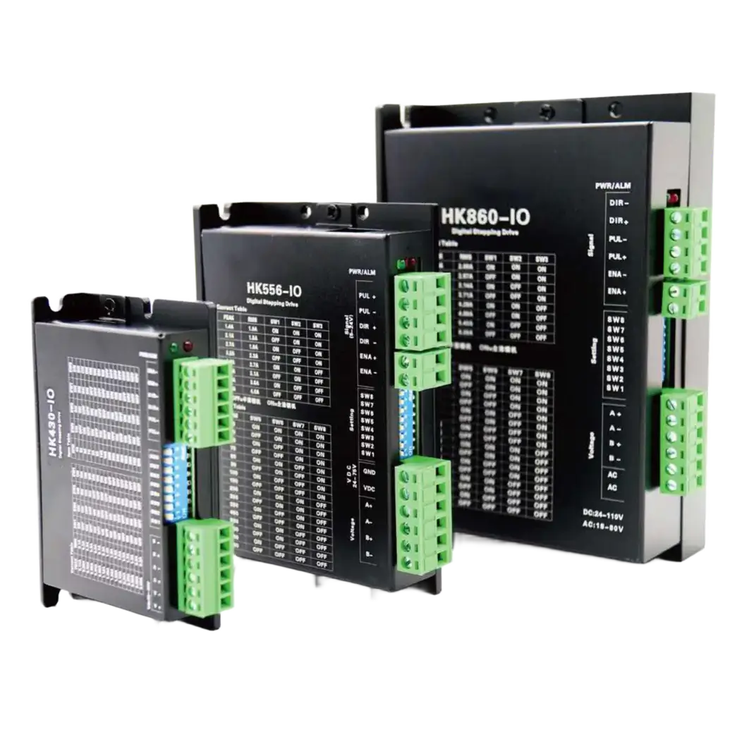
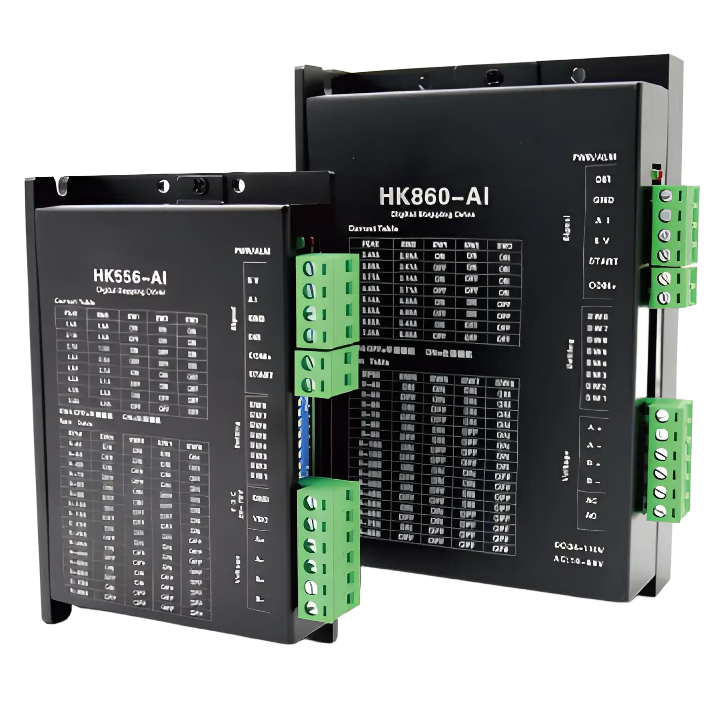
Self-Commuted Pulse Driver
| Model | HK430-IO | HK556-IO | HK860-IO | HK556-AI | HK860-AI |
|---|---|---|---|---|---|
| Phase | 2 phase | ||||
| Dial switch |
|
|
|||
| Current | 0.10-2.20A | 1.00-4.00A | 2.00-6.00A | ||
| Peak current | 0.14-3.00A | 1.40-5.60A | 2.40-7.20A | ||
| Supply voltage | DC12-40V | DC12-75V | DC24-110V AC18-80V |
DC12-75V | |
| Rotate speed | 40-850RPM | ||||
| Electric frequency signal | 5-24V compatible No series resistor required |
||||
| Control method | IO (Digital) | A (Analog) | |||
| Signal interface |
|
|
|||
| Motor wiring | A+(Black)A-(Green)B+(Red)B-(Blue) | ||||
| Debug port | type-c | RJ11 | |||
| Protection | Overvoltage / undervoltage / overcurrent | ||||
| Color | Sand Black | ||||
| Dimension | 93 x 58 x 21 | 118 x 76 x 33 | 150 x 97 x 53 | ||
| Installation size | 85 | 110 | 138 | ||
| Adaptive motor | 28/35/42 base open loop motor | 57/60 base open loop motor | 86 base open loop motor | ||
| Certificate | CE / FCC | ||||
Bus Driver
| Series | EtherCAT Bus Driver | 485 Bus Driver | |
|---|---|---|---|
| Model | EC57 | EC86 | RS57 |
| Phase | 2 phase | ||
| Dial switch |
|
|
|
| Maximum current | 5.6A | 6.5A | 5.6A |
| Supply voltage | DC24-80V AC18-60V |
DC24-80V | |
| Electric frequency signal | 5-24V compatibility No need for series resistors |
||
| Communication mode | EtherCAT | 485 | |
| Signal interface |
|
||
| Motor wiring | A+(Black) A-(Green) B+(Red) B-(Blue) | ||
| Encoder wiring | EGND (Black) VCC(Red) EA+ (Blue) EA- (Blue-Black) EB+ (Green) EB-(Green-black) | ||
| Debug port | type-c | ||
| Communication port | RJ45*2 | ||
| Protection | Overvoltage / undervoltage / overcurrent / out of tolerance | ||
| Color | Black | ||
| Dimension | 119×76×26 | 135×82×32 | 119×76×26 |
| Installation size | 112 | 127 | 112 |
| Adaptive motor | 42/57/60 base closed loop motor | 86 base closed loop motor | 42/57/60 base closed loop motor |
| Certificate | CE/FCC | ||
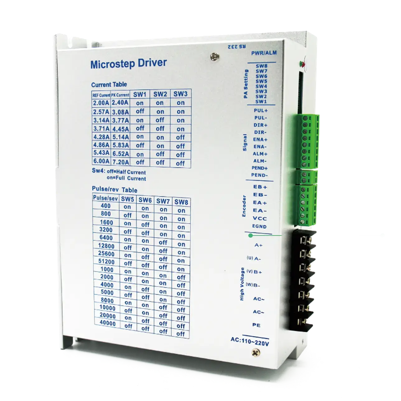
High-Voltage Driver
| Series | Maximum Pulse Frequency | Three-phase High Voltage Driver | ||
|---|---|---|---|---|
| Model | HK2280 | HB2280 | 3HK2280 | 3HB2280 |
| Phase | 2 phase | 3 phase | ||
| Dial switch |
|
|
|
|
| Current | 2.00-6.00A | 8A | ||
| Peak current | 2.40-7.20A | 13A | ||
| Supply voltage | AC110-220V | |||
| Subdivision parameter | 200-51200 P/R | |||
| Electric frequency signal | 5-24V compatible No series resistor required |
|||
| Control method | Pulse+direction/ double pulse | |||
| Maximum pulse frequency | 200kHz | |||
| Protection | Overcurrent/overvoltage/overtemperature/out of tolerance | |||
| Color | Black | |||
| Dimension | 119 × 76 × 26 | 135 × 82 × 32 | 119 × 76 × 26 | 135 × 82 × 32 |
| Installation size | 112 | 127 | 112 | 127 |
| Adaptive motor | 42/57/60 base closed loop motor | 86 base closed loop motor | 42/57/60 base closed loop motor | 86 base closed loop motor |
| Certificate | CE/FCC | |||